TERRA
TERRA is an application & microfluidic agnostic device that aims to bride the gap between microfluidics and benchtop biology. TERRA enables researchers to unload the outputs of microfluidic experiments onto standard vessels, such as microtiter plates, in order to use equipment in the lab to run further analysis. Applications include, but no limited to, unloading onto standard well plates for analysis via plate readers and single droplet analysis via a flow cytometer.
Get Started
TERRA is made up of 5 major components:
- Microfluidics
- Active XY Plane
- Control Syringes
- User Interface
The sections below detail the pieces necessary to construct its respective components, which include design and CAD files, firmware, software dependencies, and third party order information. It is important to note that TERRA does not operate microfluidic chips themselves, only the unloading of their products, so it is important to make sure that you have the necessary equipment to first run your microfluidic chip, such as pneumatic syringe pumps.
Microfluidics
Active XY Plane
Control Syringe
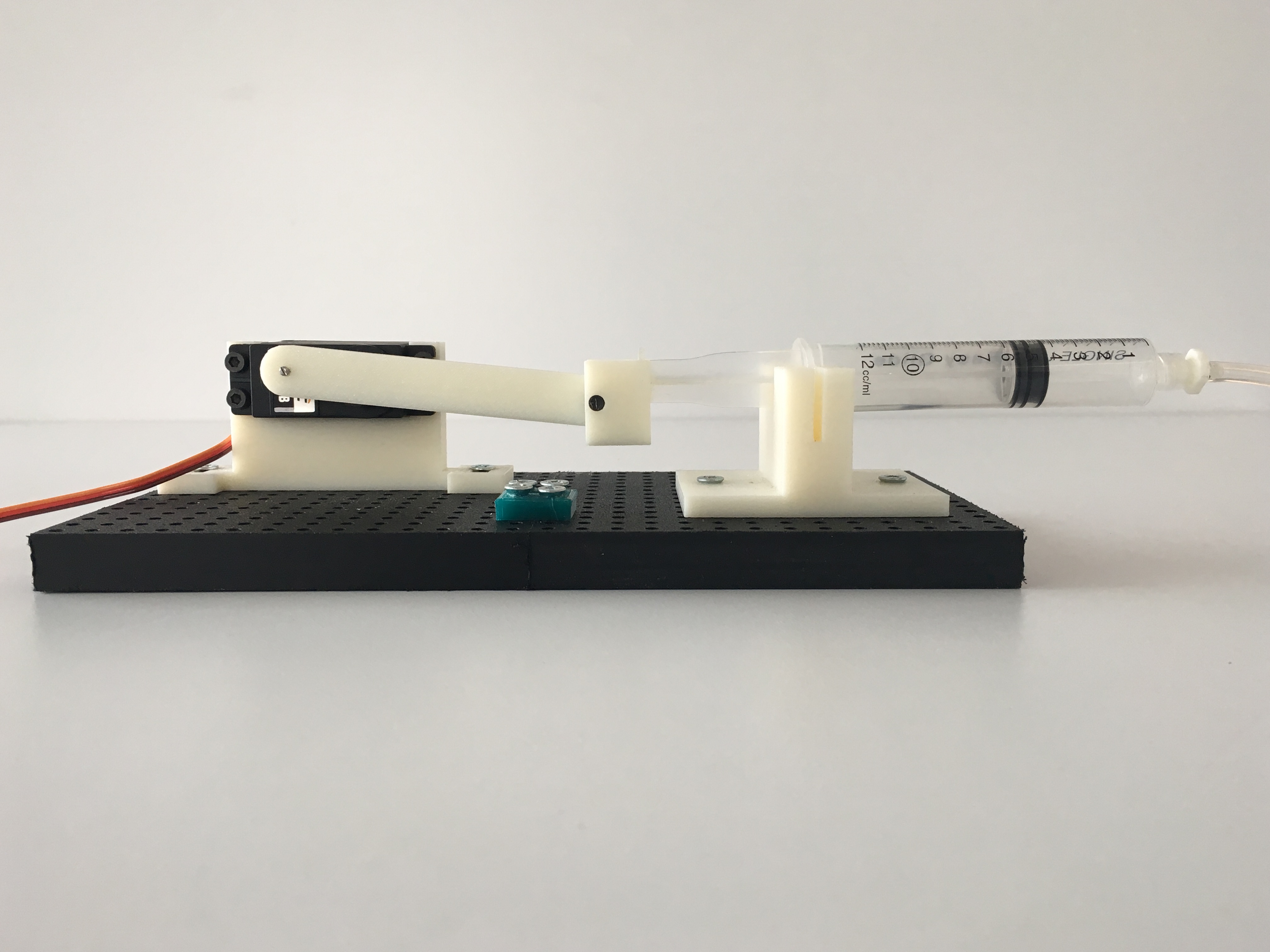
The Control Syringes are used to actuate valves on the TERRA Adapter, enabling the system to selectively dispense outputs onto the vessel. The Control Syringe system can be broken down to units, with each unit containing a servo motor, 12mL syringe, 3D printed piston, and mounting board. These units can then be combined together in a modular fashion depending on how many are required for your experiment. Every output from your microfluidic chip requires 2 Control Syringe units, one for dispensing and the other for waste. For example, a 3 output microfluidic chip experiment requires 6 Control Syringe units. Its recommended to setup a multi-unit system when first setting up TERRA in order to eliminate to need to add further Control Syringe units for future experiments.
UI
Assembly
The Active XY Plane moves the vessel of interest in a two-dimensional space allowing for selective dispension of the microfluidic experiment products. Its low-cost design and simple assembly helps researchers setup TERRA in no time. Ensure you have the following pieces before assembly:
- Servo Motors
Active XY Plane Assembly
- Cut the stainless steel rods to size (or have ordered the rods to exact sizes)
- There should be one (1) rod cut to 203 mm, one (1) to 213 mm, and two (2) to 350 mm.
- The two shorter rods will be used for vertical translation and the two larger for horizontal translation.
- Attach all bearings to the two vertical bars and the plate support.
- Each of the vertical bars have two bearings and the plate support has four.
- Make sure the bearings are attached to the side opposite of the etched teeth.
- The bearings require M4 screws.
- Place the wood so that the longer sides are horizontal and shorter sides vertical.
- Mount the support for pulley on the top left corner of the wood, making sure 8 mm hole on the side is facing towards you.
- Put the 213 mm rod through the 8 mm hole.
- Run the rod through the bearings attached to the vertical bar with teeth and attach the other end of the rod to the support for motor and pulley and mount the support.
- The holes on the side of the vertical bar should be facing to the right, parallel to the long edge of the wooden board.
- The bearings should be on top of the bar.
- Attach the two 350 mm rods to the holes on the side of the vertical bar.
- Run the rods through the bearings attached to the plate support.
- The bearings should be below the plate support and the etched teeth should be on top.
- Attach the other side of the two rods to the holes on the side of the vertical bar with motor. The bearings should be above the vertical bar.
- Run the 213 mm rod through the bearings attached to the vertical bar (without teeth).
- Attach the ends of rod to the two standard supports and mount the supports.
Control Syringe Assembly
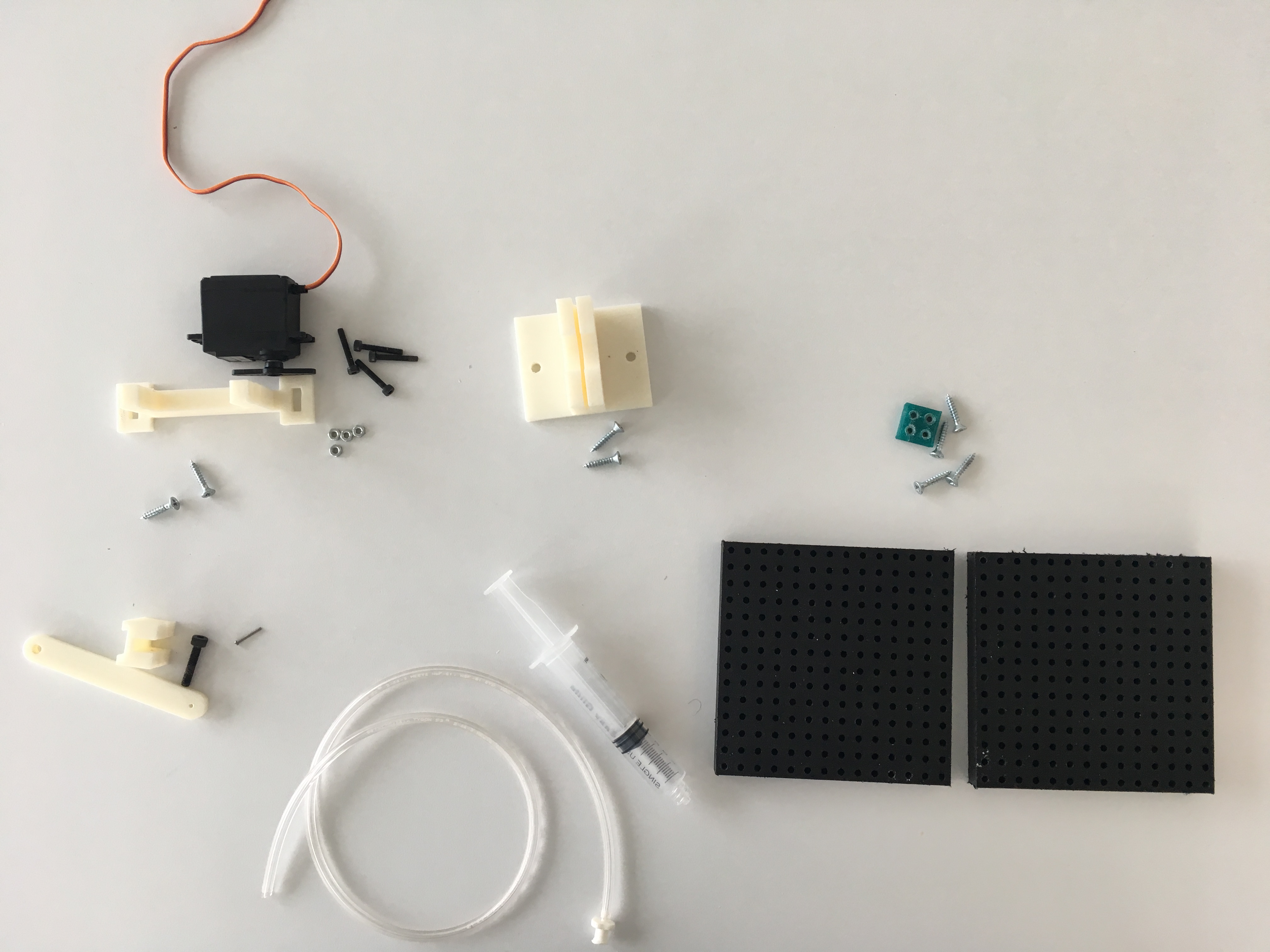
Before starting make sure you have the following pieces; links to the CAD files and order sheets can be found here.
- Servo Motor
- Servo Motor Mount
- Piston Arm
- Sryinge Connector
- Syringe Holder
- 12mL Syringe
- Base
- Base Connector
- Tubing
1
2
3
4
5
6
7
8
9
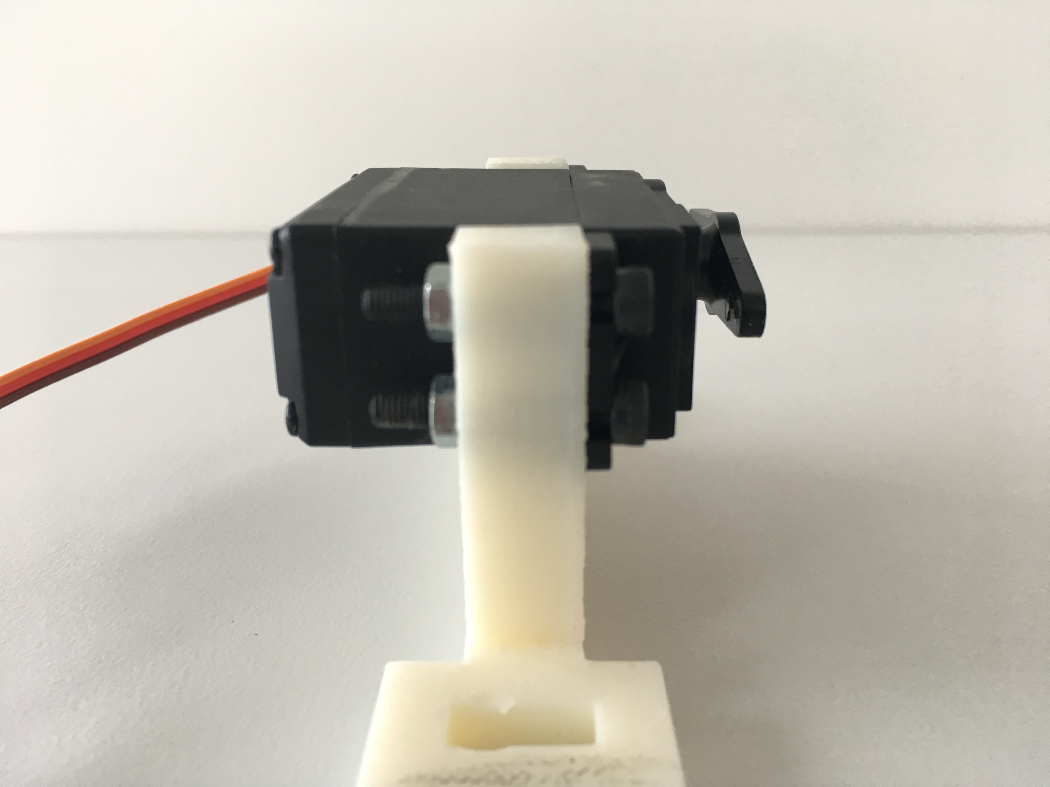
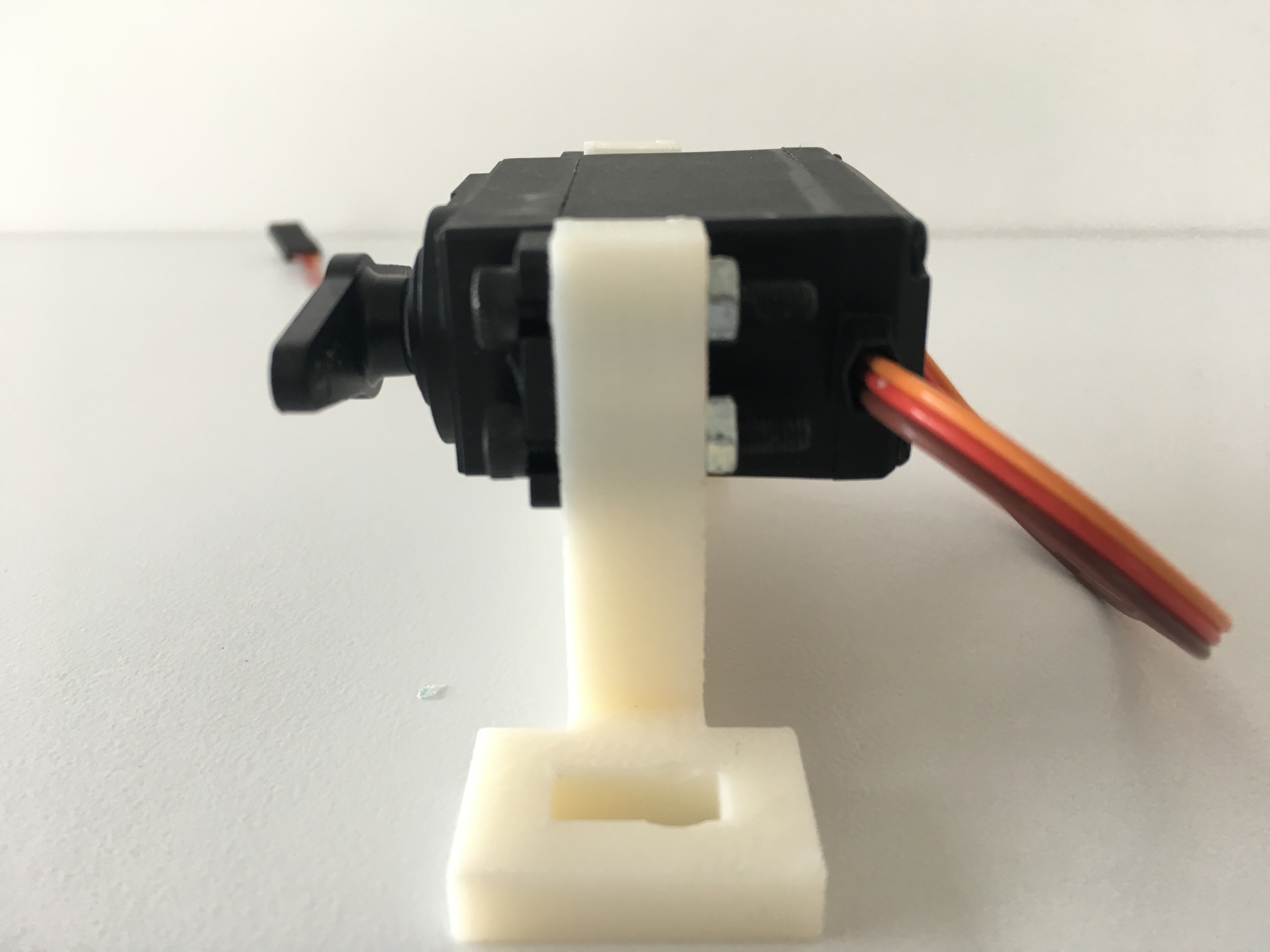
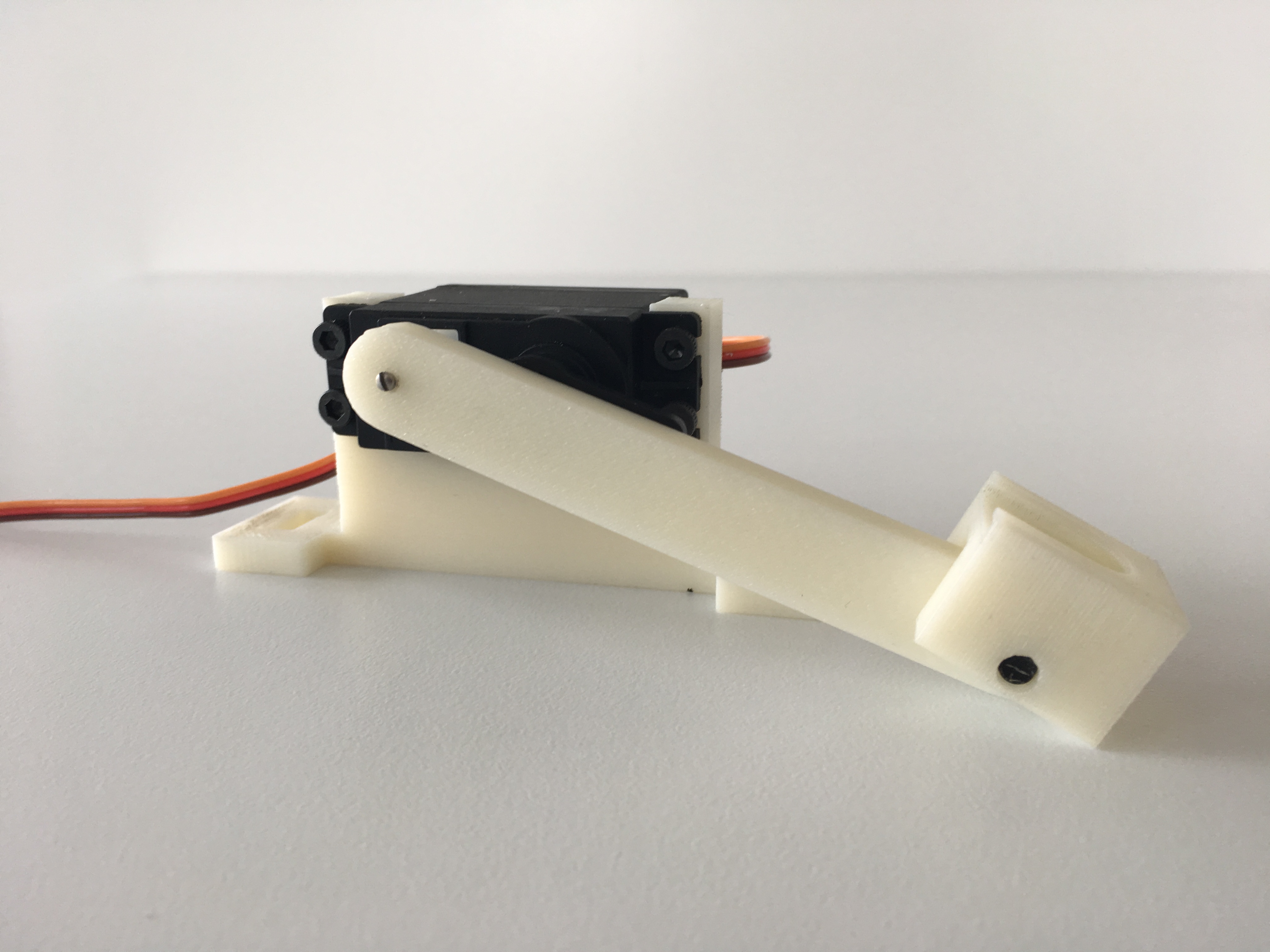
- Slide servo motor (1) into the servo motor mount (2). Screw in place by using the hex nut. Ensure that servo motor is tightly secured.
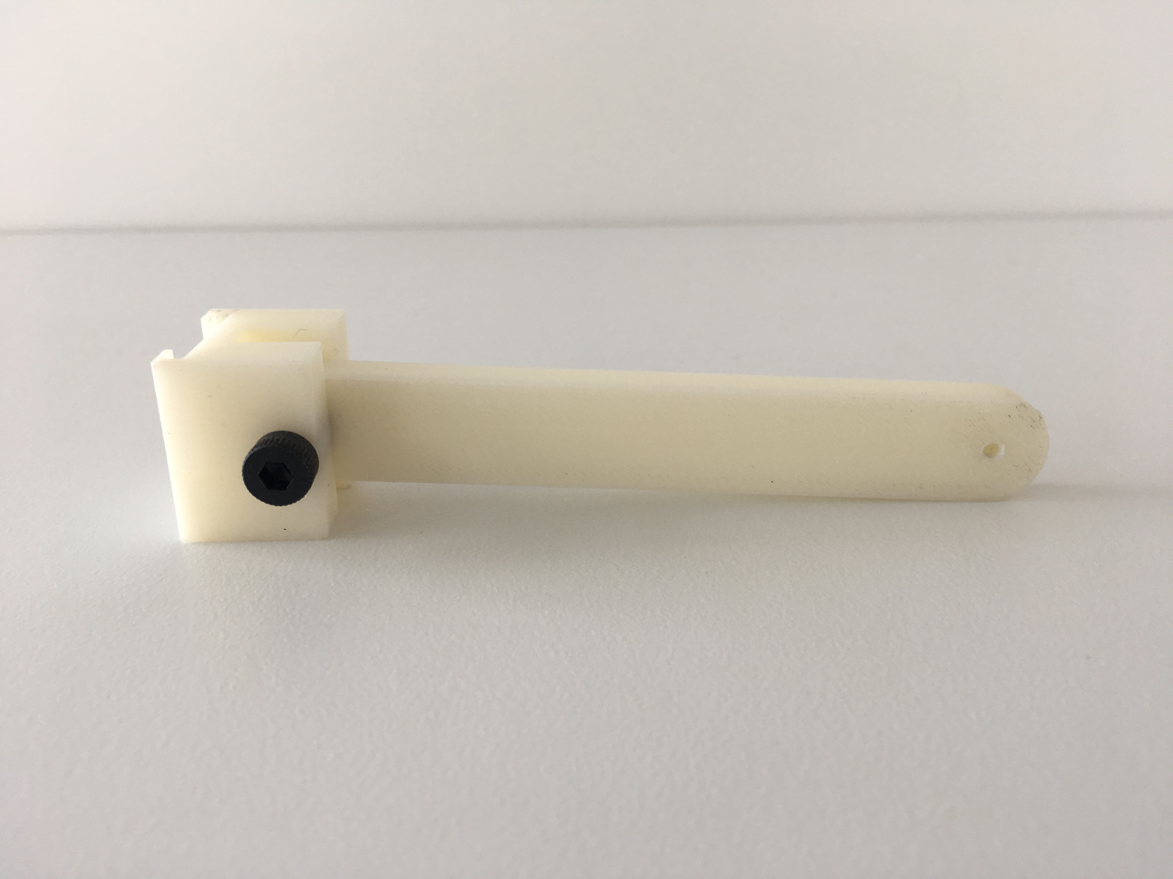
- Place piston arm (3) into syringe connector (4) on the side that has the hole for the screw. Put screw through syringe connector and piston arm and secure by screwing on hex nut. Piston arm should be able to rotate freely about the screw so do not tighten all the way.
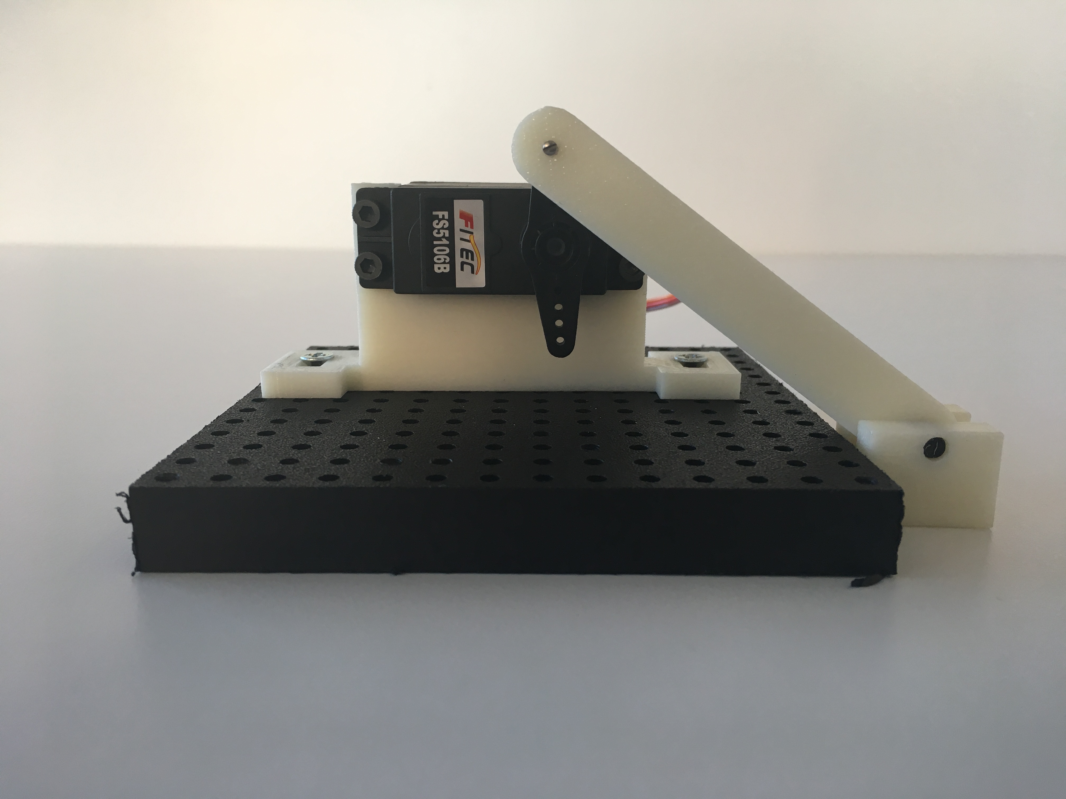
- Using screw that came with servo motor (1), attach piston arm (3) to the servo horn. Attach to the hole on the tip of the horn as shown below. When screwing in apply slight pressure due to inital lack of threading in the hole. Also make sure that the "U" shape in the syringe connector (4) is facing up.
- Connect the Adafruit 16-channel PWM/Servo Shield to the Arduino following the instructions with the shield. Once connected connect the motor to the shield and upload the Reset program to set the servo motor position to origin. This step ensures that the following placement of the servo motor and syringe holder is correct.
- Reseting to origin should place the servo motor horn vertically 90 degrees. If it is horizontal remove the horn and replace it at a 90 degree angle.
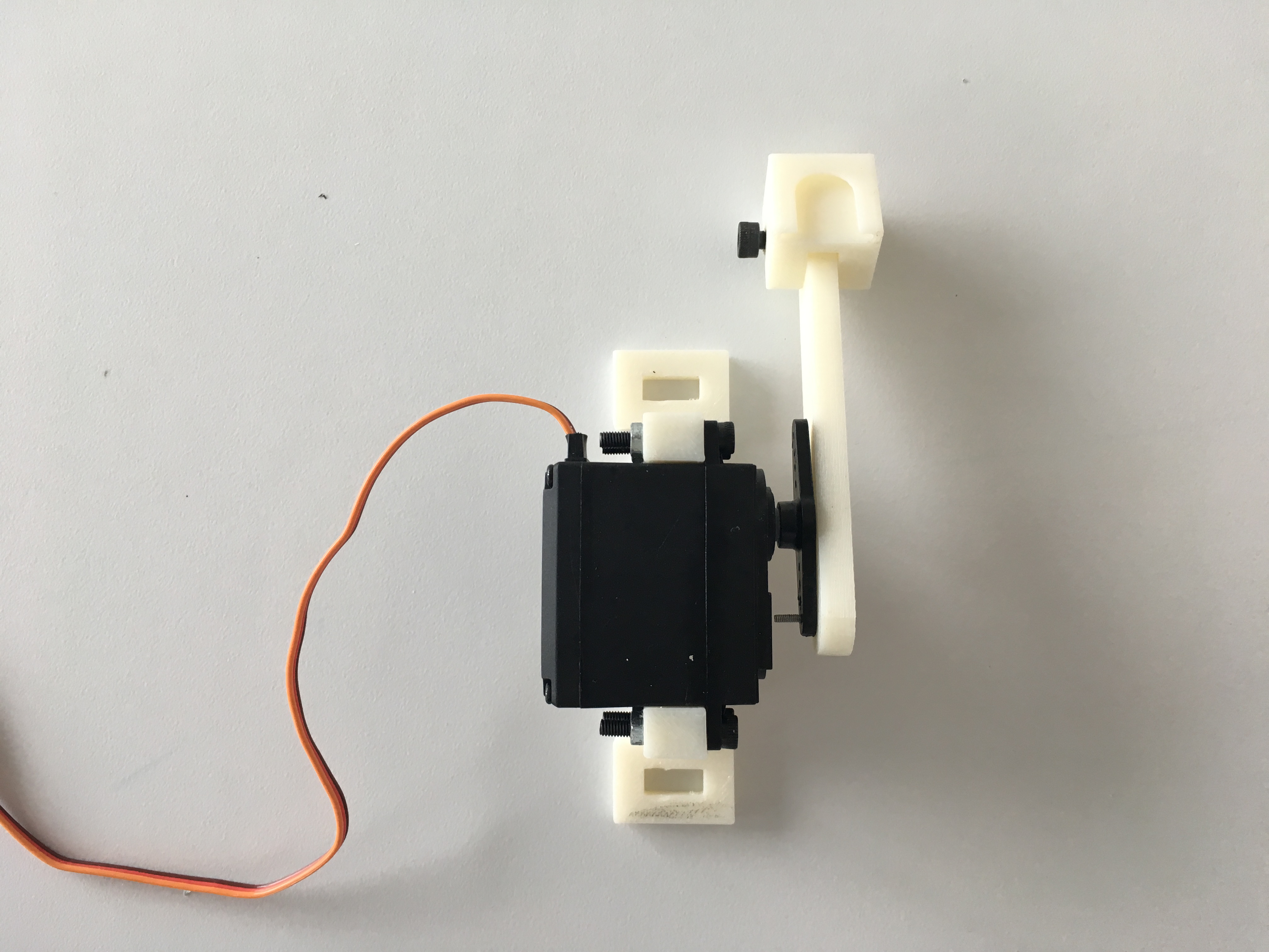
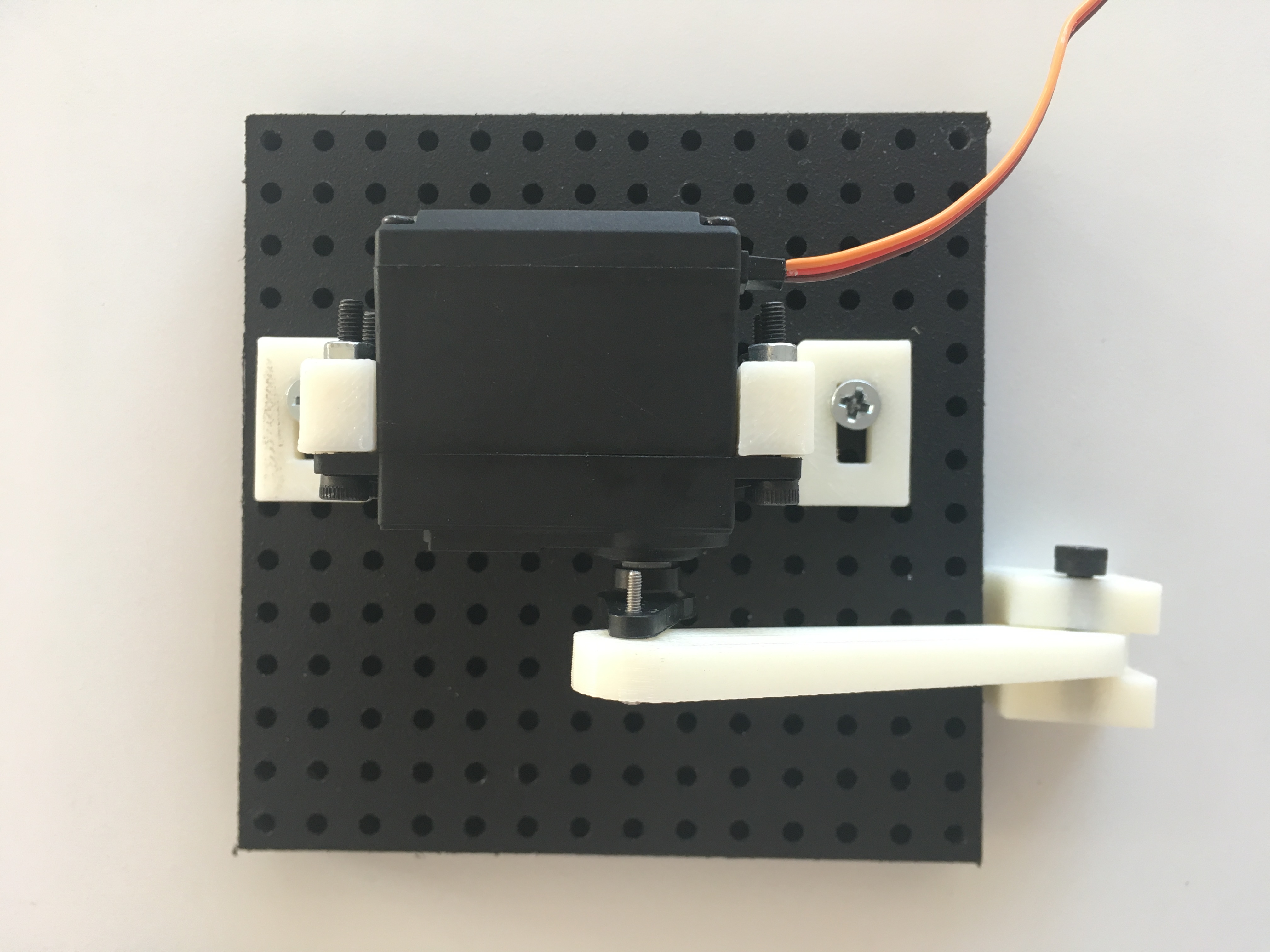
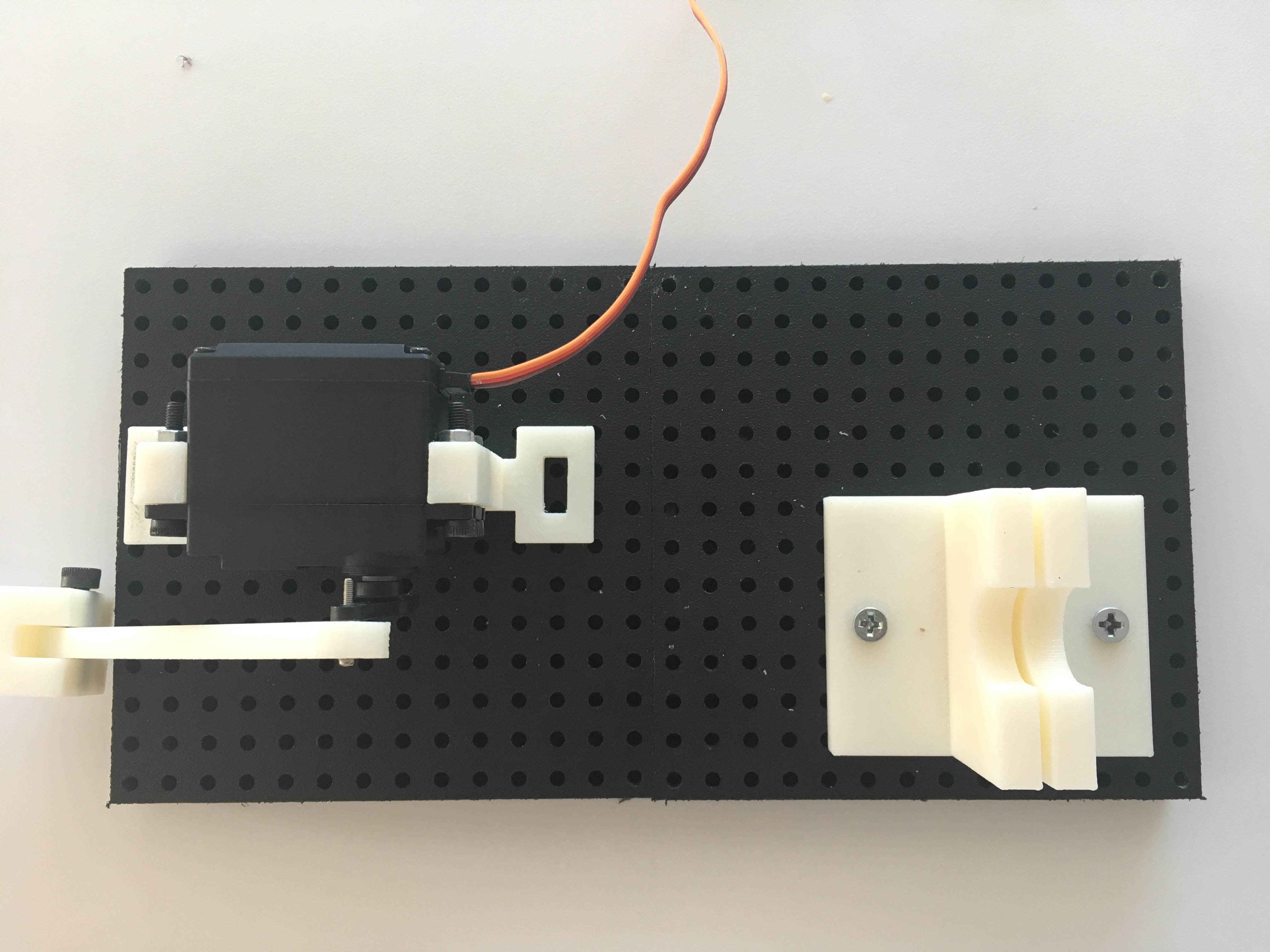
- Screw servo motor unit onto one of the bases (7) as shown below. Screw one end onto the second column of holes and the other on the third to last column on the other end. The row placement doesn't matter as long as both ends are on the same row.
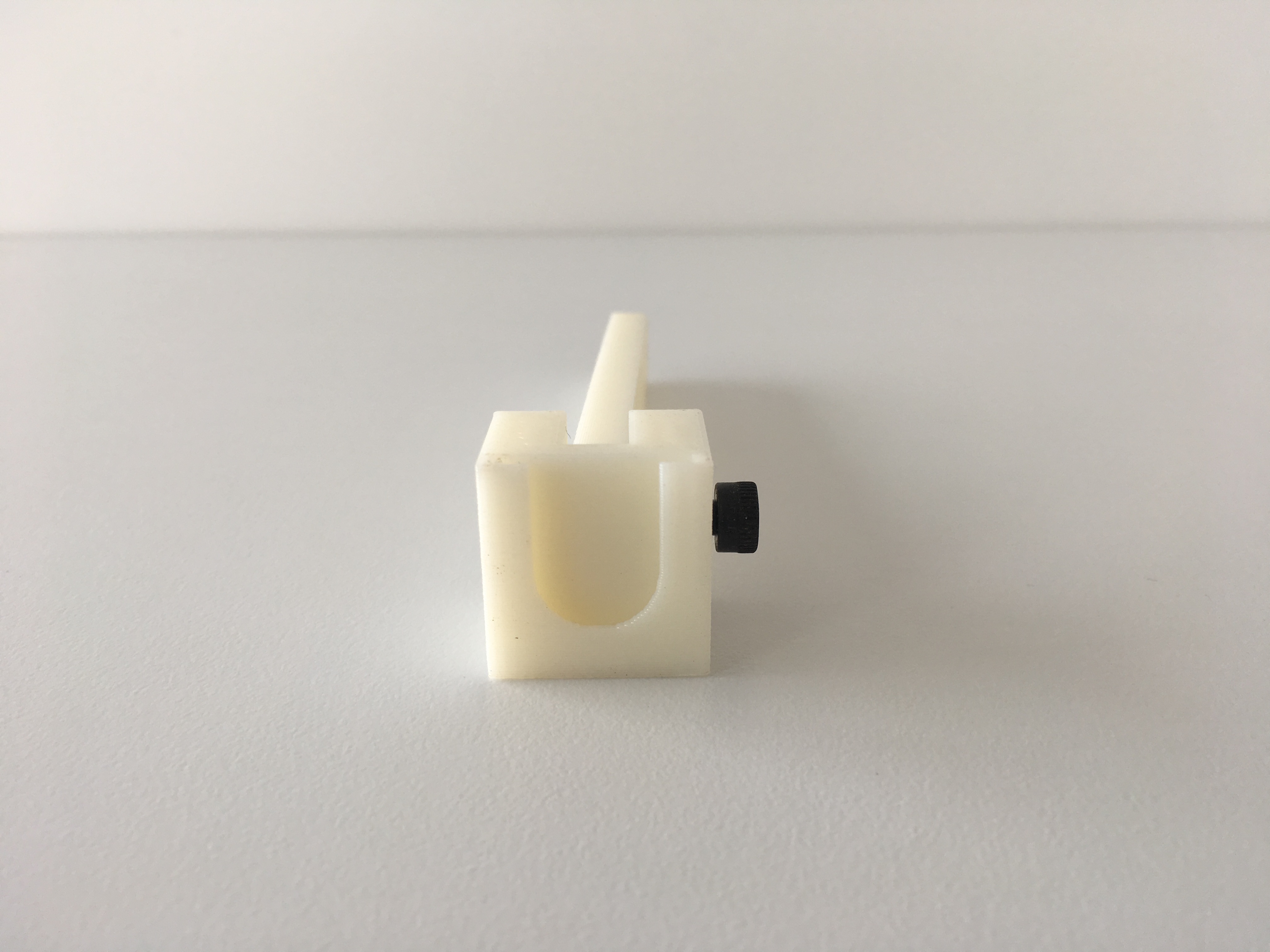
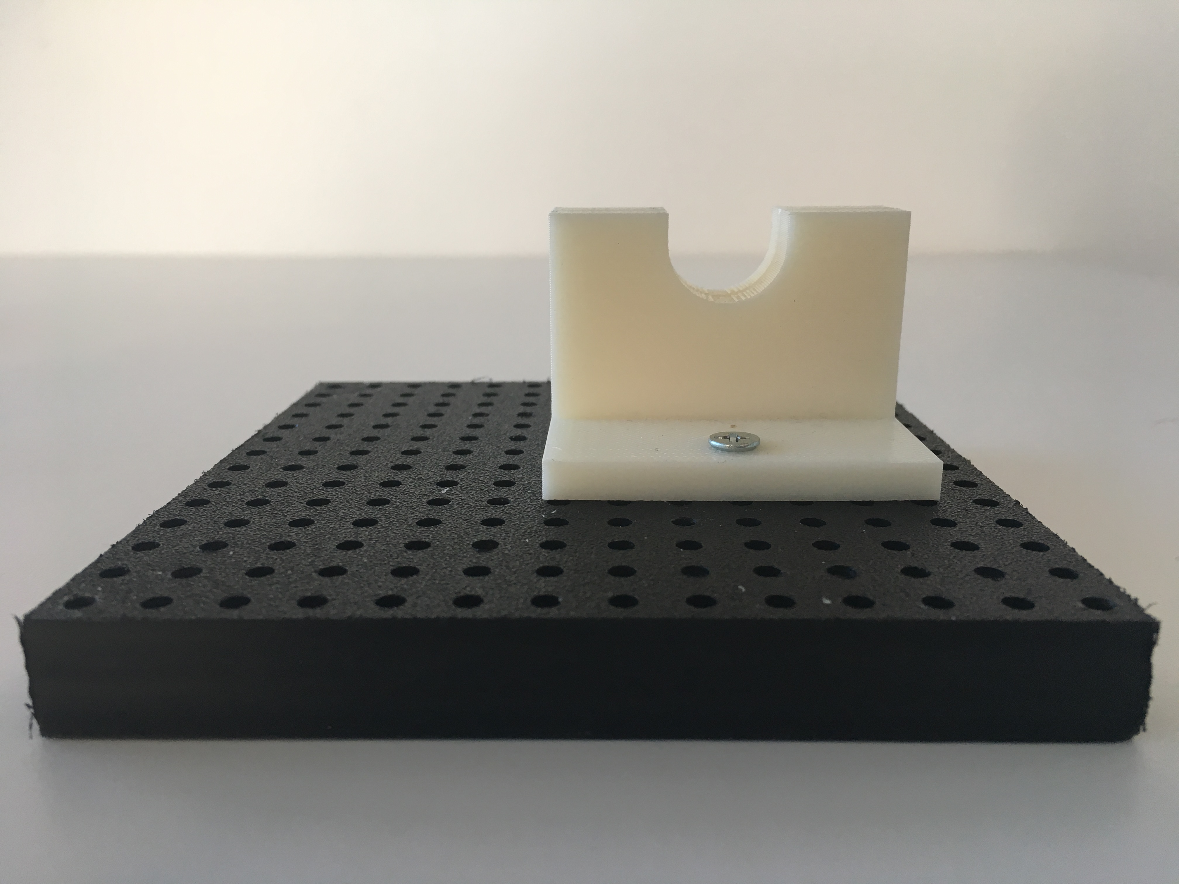
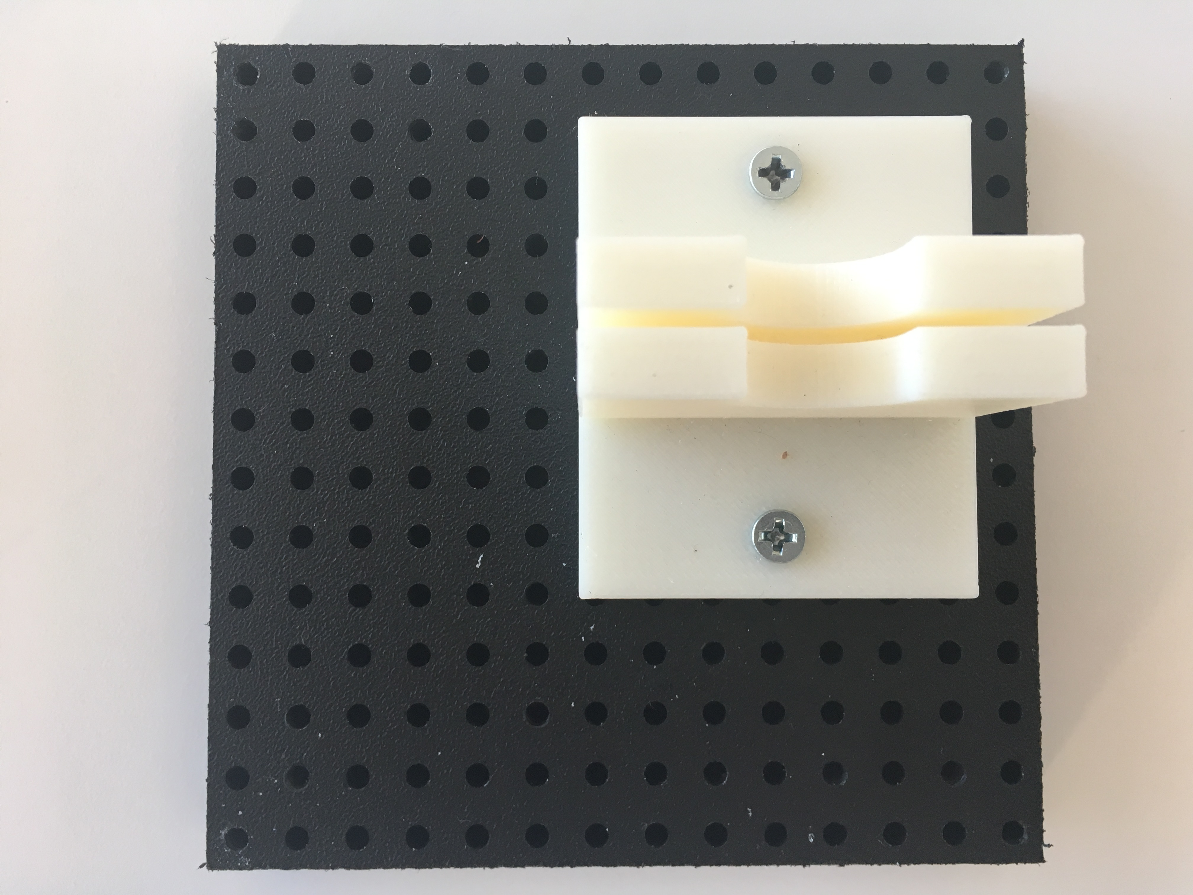
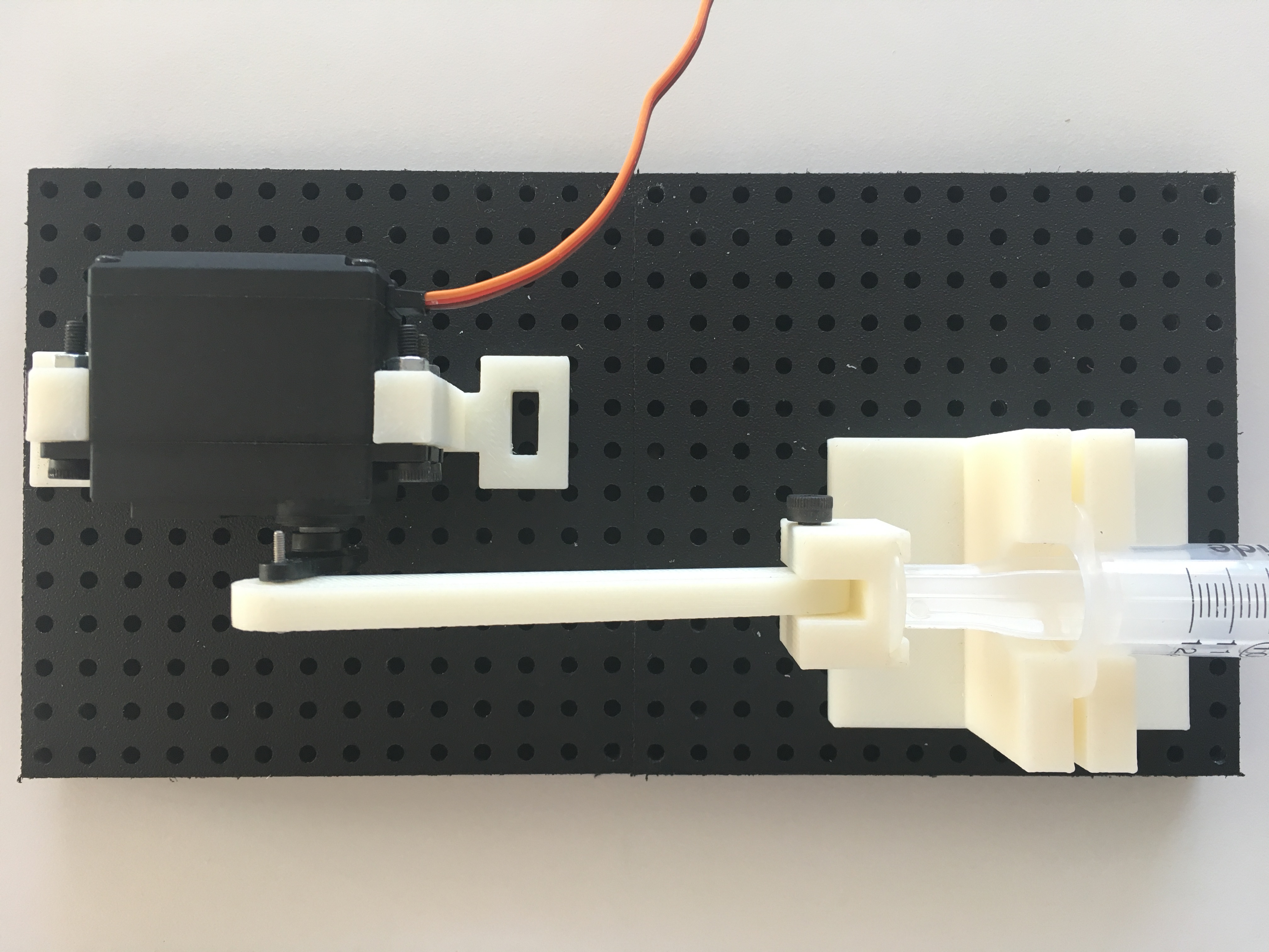
- Screw the syringe holder (5) onto the other base(7). The placement of the syringe holder should align with the piston arm (3) on the other base.
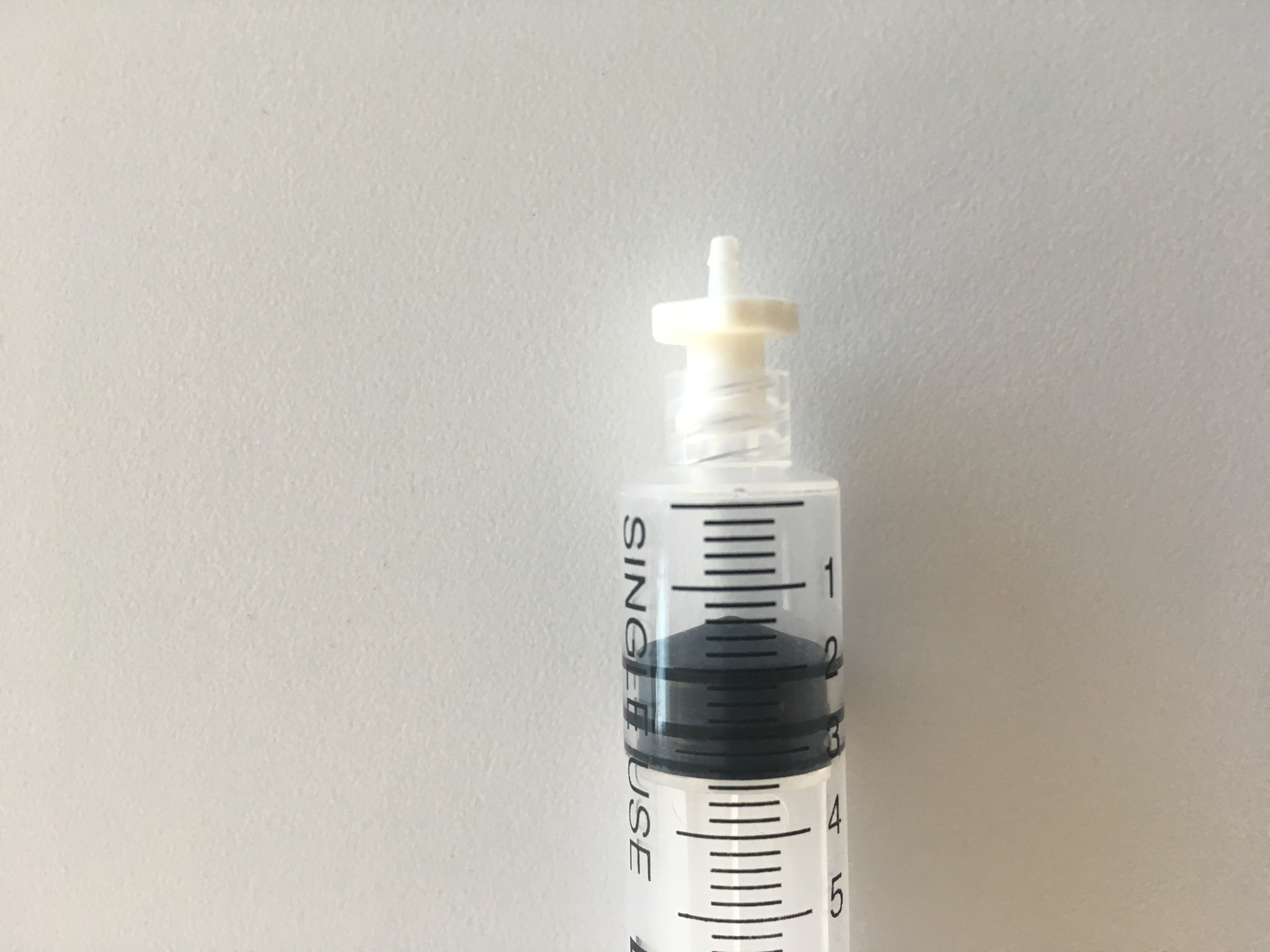
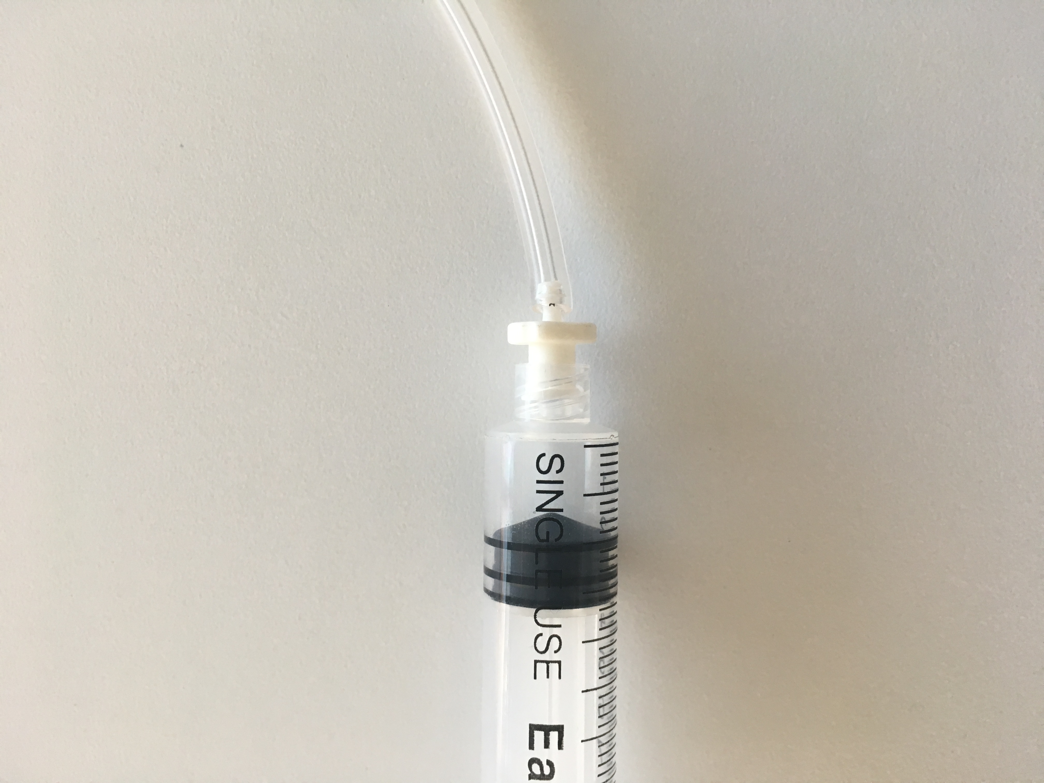
- Connect the tubing (9) to the syringe (6) via a tube connector. Twist on the tube connector onto the syringe and push into tubing, ensuring that fit is tight.
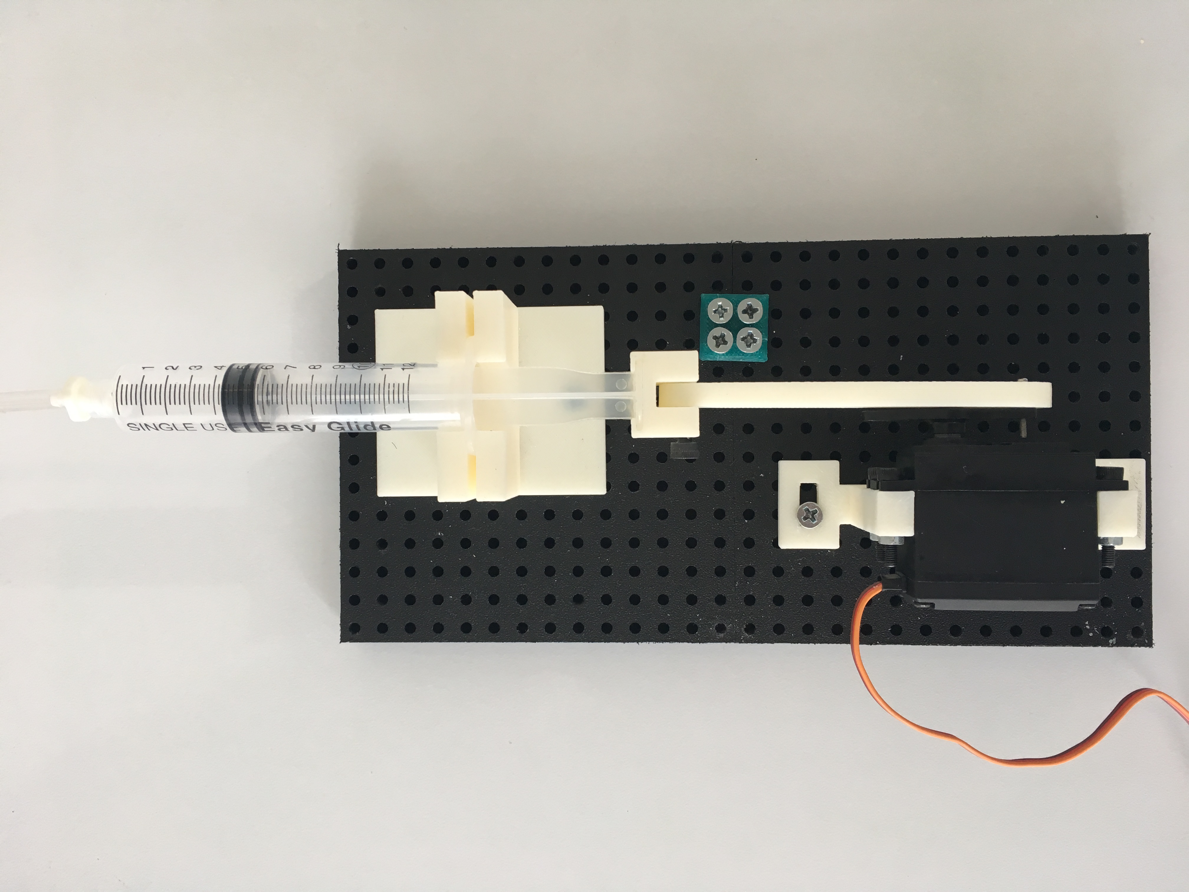
- Align the two halves of the control syringe unit so that the piston arm (3) is lined up with the syringe holder (5). Slide the assembled syringe into the syringe connector (4) by sliding the plunger of the syringe into the slot on the syringe connector. Swing over the now connected syringe over to slide the "wings" of the barrel into the syringe holder (5).
- Connect the two bases using a base connector (8).
- Connect the servo motor to the Adafruit 16-channel PWM/Servo Shield on the 0th pin.
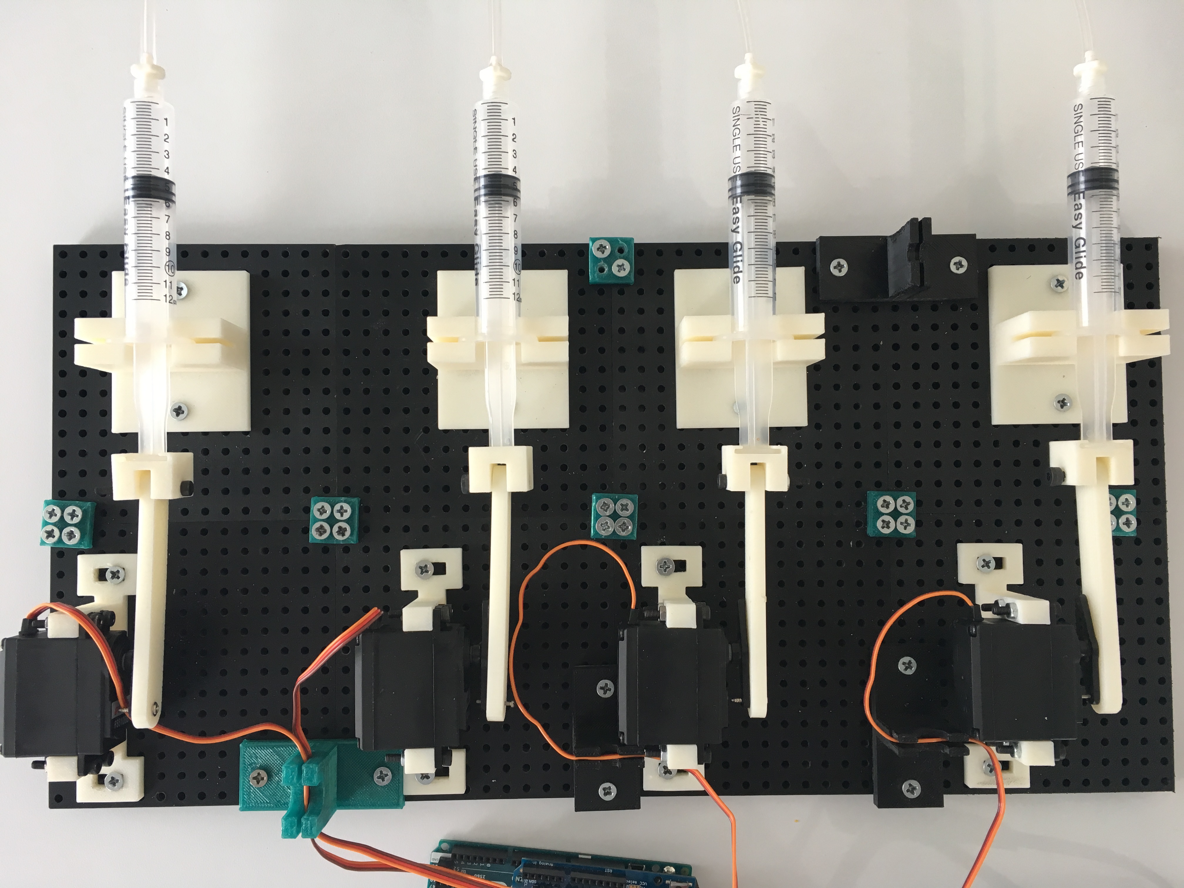
Congratulations! You've constructed a control syringe unit. These units can be connected in parallel depending on how many you need for your experiment. Just move base connectors so that they are connecting adjacent control syringe units at all connecting junctions. You can also use other pieces that have screw holes, such as syringe holders, to connect control syringe units. Connect additional units to the Arduino using the other servo pins on the shield. Below is an example of a 4 control syringe units connected together.
Software Setup
Once you have assembled the hardware components and circuitry for TERRA, the next step is to upload the necessary files onto the Arduino. There are two main files that are required; the libraries and main script. Download the lib folder found in the in TERRA's GitHub repository. After downloading, transfer these files into the Libraries folder found in your Arduino directory. Lastly, download the main.ino file found src folder in TERRA's GitHub repository. Upload the main.ino file via the Arduino IDE. If the Arduino is reuploaded with other code then you must reupload the Arduino with the main.ino file.
Microfluidic Setup
To use unload the outputs from you microfluidic chip, a TERRA Adapter is required. The number of inputs for TERRA Adapter must equal the number of outputs of your microfluidic chip. For this reason if you do not already have a TERRA Adapter that already fills this constraint you are required to make one. Using 3DuF, a web-based application for designing and creating microfluidic devices using Makerfluidics, create a TERRA Adapter chip for your run using the TERRA Adapter feature. A TERRA Adapter feature is needed for every output coming off your microfluidic chip. Visit the 2017 BostonU HW Mars team's wiki for more information regarding the construction of microfluidic chips using Makerfluidics.
Use TERRA
FAQs
Contact
For help contact the team at buigem.hw.18@gmail.com